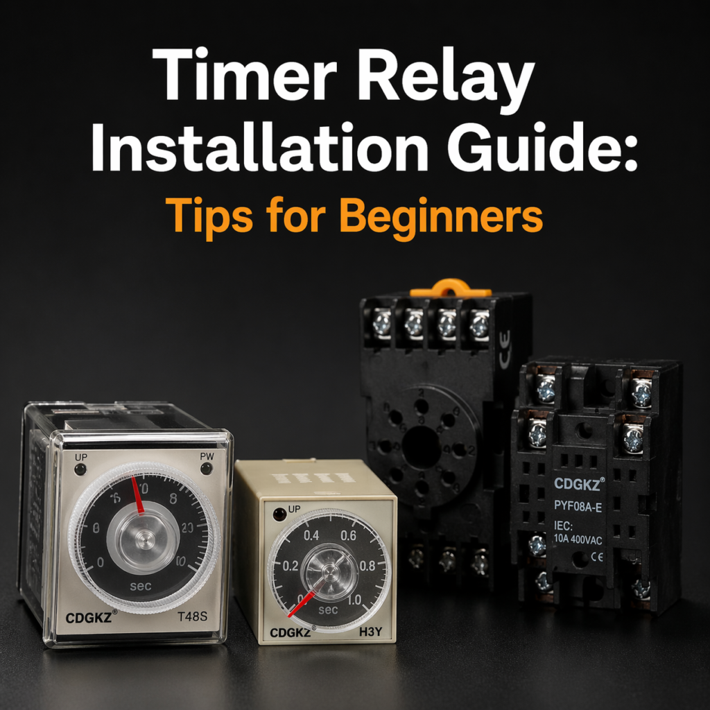
Timer Relay Installation Guide: Tips for Beginners
If you are searching for a timer relay installation guide, timer relay wiring for beginners, or how to install timer relay products without costly mistakes, the biggest problems are usually simple ones: wrong control voltage, unclear terminal identification, and choosing the wrong mount or socket. This guide explains CDGKZ timer relay installation, practical easy wiring timer relay steps, and what to check before any 24V timer relay installation or 220V timer relay wiring guide job starts.
TL;DR
- Choose the timing function before you wire anything. Mainstream timer families typically offer on-delay, off-delay, interval, cycle/flasher, and in some ranges star-delta options, and official instructions from Finder explicitly state that time scale and function should be set before energizing the timer.
- Treat voltage and mounting as separate decisions. A 24V unit, a 220V unit, a DIN rail timer, and a panel timer are not four different timing principles; they are usually combinations of supply choice, function choice, and installation format.
- Never wire by memory. On many timer relays, A1/A2 are the power terminals and B1 is a start/control input, but exact arrangements still vary by model and by manufacturer, so the datasheet or front diagram must be your final reference.
- For compliance-sensitive projects, start your document stack with the standards pages from the International Electrotechnical Commission for IEC 61812-1 and UL Solutions for UL 508A/UL 508.
Key Takeaways
- Beginners make fewer mistakes when they separate function, voltage, and mounting decisions before wiring.
- A timer relay with clear wiring diagram is usually a better first buy than the cheapest catalog line.
Learn more about timer relay operating modes and selection logic.
What to confirm before you install
A strong timer relay installation guide begins before a screwdriver touches the terminal block. First, confirm the timing mode. Official product information from Omron shows that common multifunction timers include ON delay, Flicker OFF start, Flicker ON start, Signal ON/OFF delay, Signal OFF delay, Interval, and one-shot output modes, while official pages from Schneider Electric also show dedicated star-delta and multifunction timer relays in slim DIN-rail formats. In other words, beginners should choose the logic first, not the housing first.
Second, confirm the supply voltage and start method. CDGKZ’s own timer relay sourcing guidance explains that 24V timer relay installation and 220V timer relay wiring guide searches usually map to typical control-panel supply choices, while universal-input models can reduce SKU count in mixed or export projects. Official Omron and Schneider examples also show how common 24–240 V AC/DC timer relays have become for control cabinets. That is useful for procurement, but beginners still need to identify whether their actual unit is 24 VDC only, 220–240 VAC only, or universal input.
Third, treat mounting and serviceability as part of safety and uptime. CDGKZ correctly notes that DIN rail is an installation format, not a timing function, and Omron’s H3CR specifications show that some timer families can be panel-, track-, or surface-mounted depending on the socket selected. For a first-time installer, a timer relay with socket base and a timer relay with clear wiring diagram often creates a cleaner learning curve than a crowded direct-wire replacement job. For formal compliance references, start with IEC 61812-1, which applies to time relays and coupling relays, and UL 508A, which covers industrial control panels intended for general industrial use up to 1000 V.
| Checklist Item | What to Confirm | Common Options | Why It Matters | Beginner Tip |
|---|---|---|---|---|
| Timing Function | Choose required delay or cycle mode | On-delay, Off-delay, Interval, Cycle, Star-Delta | Wrong mode causes incorrect machine sequence | Read machine logic before buying |
| Supply Voltage | Check control power input | 24V DC, 24V AC, 110V AC, 220V AC, Universal | Incorrect voltage may damage coil or fail to start | Verify with multimeter first |
| Contact Type | Check output switching requirement | SPDT, DPDT, 3PDT, NO / NC | Must match load wiring and control logic | Count required outputs before selection |
| Time Range | Choose operating delay range | 0.1s–1s, 1s–10s, 1min–10min, Multi-range | Too narrow or too wide reduces accuracy | Use middle of range for best adjustment |
| Mounting Style | Check panel space and installation method | DIN Rail, Panel Mount, Plug-in Socket | Wrong mounting causes fitting issues | Measure cabinet space first |
| Socket Compatibility | Confirm pin layout and base type | 8-pin, 11-pin, 14-pin socket base | Mismatched socket prevents installation | Compare datasheet pin diagram |
| Load Rating | Check current and voltage of output load | 5A, 10A, Resistive / Inductive loads | Underrated contacts shorten lifespan | Add safety margin of 20% |
| Environment | Check heat, dust, vibration, humidity | IP rated, sealed, industrial grade | Harsh conditions reduce reliability | Use cabinet ventilation if needed |
Key Takeaways
- Pick the timing function first, then confirm voltage, contact form, and mounting.
- A DIN rail timer and a panel timer may perform the same logic, but they install and service differently.
- Standards support the buying decision: IEC 61812-1 for time relays and UL 508A/UL 508 for panel and control-equipment context.
Timer relay wiring for beginners
If your goal is a true timer relay setup tutorial, make the process mechanical and repeatable. Step one is always to de-energize the circuit and confirm that the relay, socket, and panel layout all match. CDGKZ’s relay-socket installation guidance warns that wrong socket selection can cause loose fit, overheating, and unreliable operation, which is exactly why beginners should not reuse a “similar-looking” base without checking pin count and mounting type.
Step two is terminal identification. Omron’s official H3DK material shows the typical beginner-friendly logic used by many industrial time relays: power on A1 and A2, start on B1 and A1, NC output on 15-16, and NO output on 15-18. That mapping is one reason standardized terminal legends matter so much in easy wiring timer relay applications. It is also why a timer relay with clear wiring diagram saves commissioning time.
Step three is voltage discipline. Omron states that some H3DK power terminals do not require polarity consideration on the power supply side, but its documentation also shows precise allowable supply ranges, while Finder’s instruction sheet warns that in some DC control-start arrangements the positive polarity must be connected to B1. The lesson is simple: how to install timer relay equipment safely depends on the exact model, not on generic internet diagrams alone. A 24V timer relay installation is not automatically wired like a dedicated 220–240 VAC unit, even when the front panel looks familiar.
Step four is function setting and live testing. Finder states that time scale and function must be set before energizing the timer, and its sheet also recommends keeping wiring runs as short as possible because motors, transformers, contactors, switches, and nearby power cables can disturb or damage timer electronics. In practice, that means you should energize with a short time setting first, confirm the relay state change on the output contacts, and only then dial in the final operating delay.
Timer Relay Wiring Diagram for Beginners
Terminal Functions
Power Supply Input
(24V / 110V / 220V)
Start / Trigger Input
Common (COM)
Normally Closed (NC)
Normally Open (NO)
Key Takeaways
- Identify the socket and terminal pattern before you connect a single wire.
- Use the manufacturer’s exact terminal map, especially for start input and DC polarity details.
- Set function and time first, then test with a short delay before final commissioning.
Read more about relay socket installation and maintenance best practices.
DIN rail and panel mount installation tips
For SEO, buyers often search DIN rail timer relay installation and panel mount timer relay guide as if they were different product categories. Technically, they are usually different mechanical formats wrapped around similar timing logic. CDGKZ’s timer-relay content explicitly makes this distinction, noting that DIN rail is a cabinet-installation format, not a timing function. That is an important educational point because many beginners mistakenly compare “DIN rail relay” to “off-delay relay” as if they were parallel specifications. They are not.
The mainstream market examples support that view. Schneider’s official product pages describe slim 17.5 mm timing relays for DIN rail use, including multifunction ranges that accept 24 VDC or 24–240 VAC/DC and star-delta versions for 220–240 VAC applications. Omron’s H3DK documentation describes a 22.5 mm DIN track-mounted standard timer series, while Omron’s H3CR family can be panel-, track-, or surface-mounted depending on the socket selected. For a control-panel designer, that means mounting choice should be driven by enclosure space, replacement speed, front-access needs, and maintenance frequency.
This is also where CDGKZ becomes commercially interesting. Official CDGKZ socket pages say its push-in relay sockets are available in 4-pin, 5-pin, 6-pin, 8-pin, 11-pin, and 14-pin options, and the company markets them as tool-free, fast, and secure for modern control panels. A product page for its CDO8AN-E socket lists a 10 A, 300 V, 8-pin socket rating, while other CDGKZ pages emphasize regular sockets for standard relays and broad mounting options including PCB, DIN rail, and panel mount. For beginners, that combination supports the keyword intent behind timer relay with socket base and high quality timer relay for control panel.
| Comparison Factor | DIN Rail Timer Relay | Panel Mount Timer Relay | Socketed Plug-in Timer Relay |
|---|---|---|---|
| Installation Speed | Very fast snap-on mounting to standard DIN rail | Slower, requires panel cutout and fixing hardware | Fast after socket is pre-installed |
| Serviceability | Good, easy access inside cabinet | Moderate, rear access may be needed | Excellent, relay pulls out without rewiring |
| Wiring Space | Efficient vertical cabinet layout | Limited by panel depth and rear clearance | Good spacing depending on socket type |
| Replacement Convenience | Moderate, may need terminal removal | Low to moderate, front/rear disassembly possible | Best option for quick replacement |
| Typical Use Case | Control cabinets, automation panels, OEM machines | Operator panels, front-face equipment control | Maintenance-friendly industrial systems |
| Appearance / Access | Mounted inside enclosure | Visible on front panel | Usually inside panel with removable module |
| Best For Beginners | Yes, simple standardized installation | Only if front-panel display is required | Yes, easiest maintenance and relay swapping |
| CDGKZ Recommendation | Best for new cabinet builds | Best for equipment face control | Best for distributors & service markets |
Key Takeaways
- DIN rail and panel mount describe installation style, not timing behavior.
- Slim DIN rail models save panel space, while socketed or panel-mounted formats can simplify replacement and front access.
- Socket compatibility is not an accessory issue; it directly affects heat, retention, service time, and maintenance risk.
Why CDGKZ is a strong conversion choice
Conversion-focused copy only works when the claims match real procurement pain points. According to Zhejiang Chuangdao Electric, the company behind the CDGKZ brand, its official site positions the business as a one-stop industrial control supplier with more than 30 series and hundreds of models, and describes 18 years of expertise in industrial automation controls and low-voltage electrical solutions. The same official materials describe a 4,000㎡ automated facility, multiple certifications across the product range, and a structured custom-service workflow covering inquiry, design, sample fabrication, production, quality control, packaging, and shipment. Those are exactly the points buyers look for when screening a reliable timer relay manufacturer or OEM timer relay factory China partner.
The second conversion advantage is that CDGKZ does not try to sell a timer relay in isolation. Its own timer-relay sourcing article argues that voltage, mounting style, relay output, and socket/base style should be specified together. That is commercially sound advice. In real control panels, a weak base, unclear pin mapping, or poor replacement path can erase the value of an otherwise capable timer. This is why “relay plus socket plus mounting method” is more persuasive than a relay-only product pitch for industrial timer relay supplier China traffic.
The third advantage is positioning. CDGKZ’s official homepage explicitly markets cost-effective alternatives and fast delivery, while its push-in socket pages stress factory-direct pricing, customization, and fast turnaround. Used carefully, that supports the phrases multifunction timer relay supplier, timer relay fast delivery supplier, and affordable timer relay alternative without overpromising performance beyond the datasheet. In other words, whether a buyer types CDGKZ Timer Raley, CDGKZ timer relay installation, or buy CDGKZ timer relay, the conversion message should stay grounded: competitive cost, compatible sockets, practical wiring support, and OEM responsiveness.
Key Takeaways
- CDGKZ’s strongest story is one-stop sourcing: relays, sockets, customization, and production support.
- The brand’s sales argument is strongest when it emphasizes socket compatibility and mounting practicality, not just timing functions.
- Use “cost-effective” and “fast delivery” as official brand-positioning language, and let the technical claims come from the actual wiring logic and specifications.
Explore custom relay socket and OEM manufacturing services.
FAQ
What is the safest way to start a first-time 24V timer relay installation?
Start by confirming the timing function, the rated supply voltage, and the exact terminal arrangement on the relay or datasheet. For many industrial units, A1/A2 are the supply terminals and B1 is the start input, but you should still confirm the output contact mapping and any DC polarity notes before energizing the circuit. Testing with a short delay first is safer than commissioning at the final delay value.
Can a 220V timer relay be wired the same way as a 24V model?
Sometimes the control logic looks similar, but you should never assume the wiring is identical. Schneider shows dedicated 220–240 VAC star-delta versions as well as 24 VDC or 24–240 VAC/DC multifunction models, while Omron shows broad universal-input timer families and model-specific terminal behavior. A generic 220V timer relay wiring guide cannot replace the exact datasheet for the installed unit.
When should I choose a timer relay with socket base?
Choose a timer relay with socket base when fast replacement, easier maintenance, or reduced rewiring matters more than the lowest upfront part cost. Omron’s H3CR platform explicitly supports mounting that depends on the socket selected, and CDGKZ’s own content stresses that matching the socket to the relay’s pin configuration and mounting style is critical for safe, reliable operation.
Key Takeaways
- The safest beginner install starts with terminal verification, not with assuming a familiar layout.
- 24V and 220V units may share similar logic, but their rated supply ranges and control details can differ a lot.
- Socket-base formats are usually worth it in maintenance-heavy cabinets.
Conclusion and call to action
In summary, a successful timer relay installation starts with getting the basics right: choose the correct timing function, confirm the supply voltage, verify terminal wiring, and select the best mounting format for your panel. Whether you need a 24V timer relay, 220V timer relay, DIN rail timer relay, or a socket-base timer relay, careful selection prevents downtime, wiring errors, and unnecessary replacement costs. For beginners and professional panel builders alike, a timer relay with a clear wiring diagram and reliable socket compatibility makes every installation faster and safer.
If you are looking for a cost-effective and dependable alternative to major brands, CDGKZ offers high-quality timer relays, matching sockets, OEM customisation, and fast factory delivery. We support distributors, machine builders, and industrial control projects worldwide with practical solutions designed for real applications.
Ready to upgrade your control panel or source a reliable supplier?
Contact CDGKZ today for:
- Free product recommendation based on your voltage and timing needs
- Wiring diagram and socket matching support
- OEM / ODM branding service
- Fast quotation and competitive factory pricing
- Sample orders for testing before bulk purchase
Send us your inquiry now and buy CDGKZ timer relays with confidence.
