Industrial Control Relay Sockets: Key Features & Selection Guide
Introduction: Industrial control relay sockets are essential yet often overlooked components in electrical control systems. They securely house electrical control relays (the switches that control circuits) and provide convenient connection points to the rest of the circuit. In industrial automation, using the right industrial relay socket can greatly improve system reliability and simplify maintenance. Without a proper socket, replacing a failed relay means rewiring, which is time-consuming and prone to errors. (Note: The term “industrial electrical sockets” here refers to relay sockets for control systems, not high-voltage power outlets.) In this guide, we’ll explore the types of industrial automation socket designs, how to choose the best one for your needs, and best practices for installation in control system relay socket applications.
TL;DR – Key Points:
– What They Are: Industrial relay sockets are specialized bases that hold and connect electrical relays for control systems, enabling quick relay replacement and reliable connections in automation systems.
– Design & Features: These sockets are built heavy-duty to handle high-power and high-voltage relays, with robust insulation, secure clips, and standardized pin layouts for different relay types.
– Selection Factors: Choosing the right industrial control relay socket involves matching the socket’s voltage/current rating, pin configuration, and mounting style (DIN rail, panel, PCB) to your relay and application.
– Installation Matters: Proper industrial relay socket installation – mounting, wiring, and securing the relay – is crucial for safe, reliable operation. Using the correct socket simplifies maintenance and reduces downtime in automation systems.
Understanding Industrial Relay Sockets and Their Importance
An industrial control relay socket is a specially designed holder that a control relay plugs into. It serves as the interface between an electrical relay and the control wiring, providing a secure mechanical and electrical connection. In practice, the relay socket mounts to a panel or DIN rail and has terminals (screw clamps, spring clamps, etc.) where you attach wires from the control system. The relay (often called an electrical control relay or simply control relay) then plugs into the socket, connecting its coil and contact pins to those terminals. This arrangement allows the relay to be replaced easily without disturbing any wiring – a big advantage for maintenance and troubleshooting in industrial settings.
Importantly, industrial automation sockets (relay sockets used in factory automation) are built to keep the relay firmly in place even in harsh conditions. Vibration, heat, and electrical noise are common in industrial environments. A quality control system relay socket ensures the relay won’t shake loose and that electrical connections remain solid over time. It also often includes features like retaining clips or springs to lock the relay in, plus markings for each terminal to reduce wiring errors. Without a proper socket, technicians would have to hard-wire relays, making replacements cumbersome and increasing the risk of wiring mistakes or downtime.
Another reason these industrial relay sockets are so important is safety and reliability. They provide insulation and spacing between the relay’s live contacts and the panel or DIN rail, reducing the chance of shorts or electric shock. Many sockets are made from flame-retardant materials and designed to withstand high voltages and currents safely. In industries like manufacturing, energy, or building automation, dozens of relays might be present. Using standardized electrical relay socket bases means each relay can be swapped out quickly, minimizing production downtime if a relay fails. In short, an industrial relay socket is a small component that solves a big pain point: it makes electrical relay for control systems both plug-and-play and dependable, which is crucial for keeping automated processes running smoothly.
Key Takeaways:
– Purpose: Industrial relay sockets hold control relays securely and link them to the system wiring, allowing easy relay replacement without rewiring.
– Reliability: These industrial electrical sockets (relay bases) prevent loose connections, ensuring stable performance even in high-vibration industrial environments.
– Safety: A good socket provides insulation and standardized terminals, enhancing safety and reducing errors in electrical control systems.
Learn more: What is an Electrical Control Relay?
Design Features of Heavy-Duty Industrial Relay Sockets
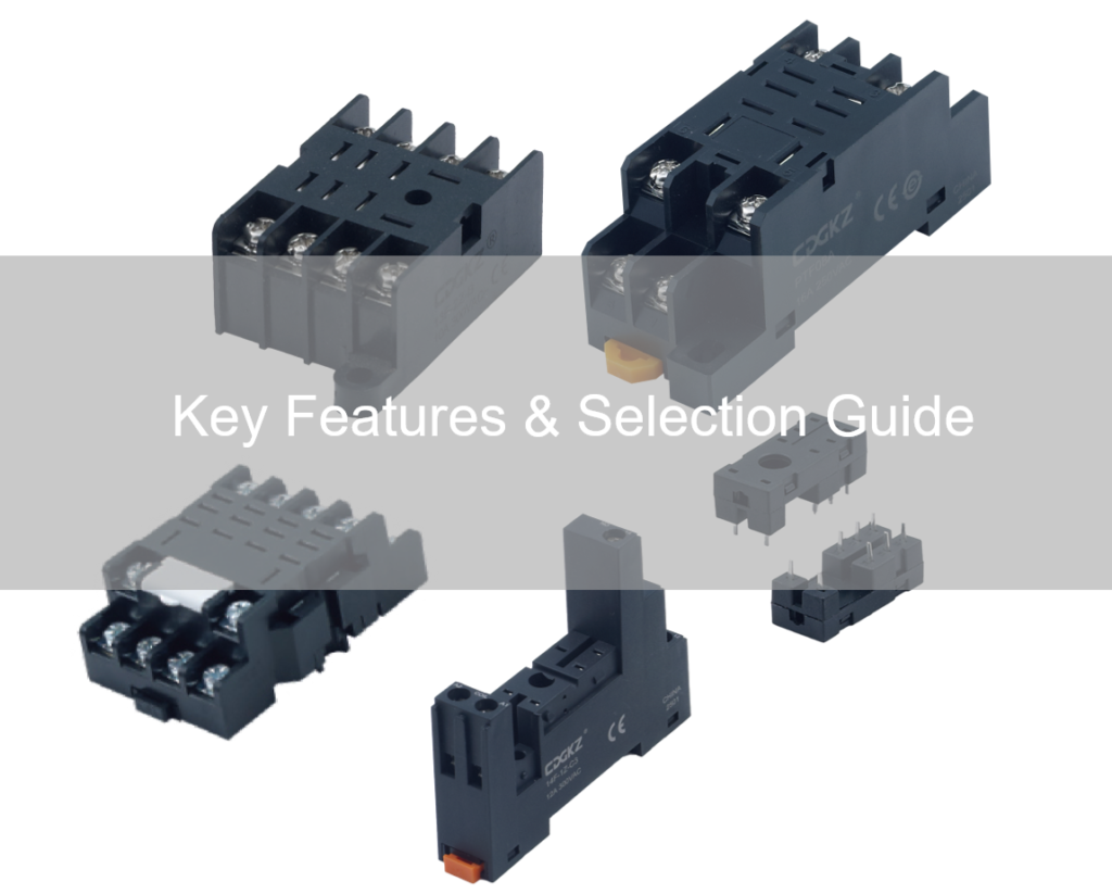
Figure: A heavy-duty DIN-rail mount industrial control relay socket (with plug-in relay and orange retaining clip). Such sockets feature secure locking clips, clearly labeled coil terminals (A1, A2) and contact connections, and durable insulating bodies designed for high-voltage use.
Industrial relay sockets are engineered with heavy-duty construction and high-quality materials to withstand demanding conditions. The socket base is typically made of a robust, flame-resistant plastic (such as PA66 nylon or thermoset resin) that can tolerate high temperatures and electrical stress. Metal contact parts (the clips or terminals that interface with the relay pins) are often plated with nickel or tin to resist corrosion and ensure a reliable electrical connection over time. These design choices let a heavy-duty relay socket handle the heat and wear of continuous operation, especially in high-power relay socket applications where currents can be large.
One key design feature is the accommodation of high voltage and current. Industrial sockets are usually rated for the same or greater voltage and amperage as the relays they host (commonly 5A to 30A, and control voltages from 24 V up to 240+ V AC/DC). For example, many heavy-duty sockets provide reinforced insulation and spacing to safely handle high voltage relay socket use without arcing. Some sockets carry international safety ratings: a typical industrial relay socket might conform to IEC standards for insulation coordination and ingress protection. For instance, a Schneider Electric relay socket is rated IP20 (finger-safe per IEC 60529) and meets IEC 61984 connector standards, while also being UL Recognized and CSA Certified. These certifications indicate the socket’s design has been tested for safety and reliability in industrial control environments.
Mechanical design features are also important. Most industrial relay sockets include a retention clip or latch to lock the relay in place. This prevents the relay from vibrating loose on a moving machine or during panel shipping. They often have guide slots or polarization tabs, ensuring the relay can only be inserted in the correct orientation (preventing miswiring). Many sockets even accommodate add-on modules – for example, pluggable surge suppression circuits or indicator LEDs that snap into the socket alongside the relay. Such modules protect the system from voltage spikes (with diodes or MOVs) and provide visual status indication. The electrical relay socket design must account for these accessories by providing extra slots or terminals (e.g., a spot for a transient suppression diode across the coil terminals). High-end designs may also incorporate test buttons or manual release levers on the socket, allowing technicians to manually operate or remove the relay easily for testing purposes.
Additionally, industrial relay socket features include the terminal configuration. Terminals can be screw-type (with screws to clamp down on wires) or spring cage (push-in) type. Screw terminals are common and very secure for heavy-duty relay socket designs, often accommodating thicker gauge wires for high-current connections. Spring terminals enable faster installation and are vibration-proof (since they can’t loosen like a screw might). The socket’s footprint is standardized to match the relay: common formats include 8-pin octal, 11-pin circular, or 14-pin square bases, among others. Each format supports certain relay contact arrangements (SPDT, DPDT, 4PDT, etc.). The electrical relay control socket must precisely align with the relay’s pin layout; thus, manufacturers design sockets specifically for their relay families, although many sockets will fit any relay of a standard type. Overall, the design of industrial relay sockets focuses on durability, safety, and ease of use, making them a reliable connector between the automation relay and the control wiring.
Key Takeaways:
– Rugged Build: Heavy-duty industrial relay sockets use flame-retardant insulators and plated metal contacts, allowing them to handle high voltages and currents safely.
– Smart Design: Features like locking clips, keyed inserts, and space for surge suppressors/LED modules are built in to enhance reliability and ease of maintenance.
– Standards Compliance: Quality sockets meet industry standards (e.g. IEC, UL, CSA), providing IP20 touch-safe terminals and verified insulation for use in control panels.
Learn more: Industrial relay quality standards and safety certifications.
Industrial Relay Socket Selection: Key Factors to Consider
Choosing the right industrial relay socket for your needs is crucial for both safety and performance. Here is a selection guide covering the main factors to consider:
- Voltage and Current Rating: Always match the socket’s electrical ratings to or above the requirements of your circuit. The socket should handle the maximum voltage and current that will pass through the relay’s contacts and coil. For instance, if you have a high-power 20A relay controlling a motor, use a high-power relay socket rated beyond 20A for safe operation. Exceeding voltage limits can lead to arcing or insulation failure, so ensure the socket’s rating meets your system’s needs. (Operating within the specified voltage/current limits prevents overheating and premature failure.)
- Relay Compatibility (Pins and Form): Relays come in various pin configurations (such as 5-pin, 8-pin octal, 11-pin, 14-pin, etc.) and contact arrangements (SPDT, DPDT, 4PDT, etc.). The socket must exactly fit the relay’s pin layout. Check the electrical relay for control systems you’re using and note its base type. An 11-pin relay, for example, requires an 11-socket base. Additionally, some relays have unique keying – for instance, square vs. round pins or notches to prevent incorrect insertion. Make sure to choose a socket specifically listed for your relay series or a universal relay socket that matches the same standard. Using an incompatible socket will either physically not fit or could connect the wrong pins, causing malfunctions.
- Mounting Style: Consider how and where the socket will be mounted in your application. The main mounting types are DIN rail, panel mount, and PCB mount. DIN rail sockets clip onto standard 35 mm metal rails commonly found in industrial control cabinets – they are ideal for modular automation relay socket setups and make it easy to reposition or replace components. Panel mount sockets have one or more screws or clips so they can be attached to a chassis or enclosure wall; these are common in vehicles or equipment where a rail isn’t used. PCB mount sockets are designed to be soldered directly onto a printed circuit board (often for smaller relays in instrumentation or appliances). Choose the style that fits your system’s construction. For example, in a factory control panel, a DIN rail relay socket for automation systems is often preferred for neat organization. In a custom PCB control board, a PCB relay socket saves space. Each has advantages, but the key is to select a socket your installation can accommodate easily.
- Terminal Type: Select the wiring terminal style based on your maintenance and wiring needs. Screw clamp terminals are very secure and handle larger wire gauges – good for high-power and for environments with vibration (the screw can be retightened if needed). Spring clamp (push-in) terminals allow quicker wire insertion and are maintenance-free (they won’t loosen over time), which is great for fast assembly and frequent modifications. Some sockets even offer quick-connect blade terminals for slide-on crimp connectors, useful in automotive or plug-and-play contexts. Ensure the socket’s terminal type aligns with your wiring practices. For instance, in an automated assembly system, push-in terminals might reduce wiring time significantly. In contrast, if you expect to land multiple wires or very thick wires per contact, screw terminals might be better.
- Environment and Durability: Evaluate the conditions the socket will face: temperature extremes, humidity, vibration, exposure to dust or chemicals, etc. Choose a socket made of materials and design suited to those conditions. For high-temperature areas (near furnaces or engines), ensure the socket’s plastic is high-temperature rated. In high-vibration applications (on machinery or vehicles), look for a socket with strong retention clips and possibly heavy-duty relay socket versions marketed for vibration resistance. If moisture or dust is present, consider sockets with protective covers or at least IP20 finger-safe design to minimize accidental contact and contamination of the terminals. Also check if the socket is advertised as flame-retardant or shatterproof for demanding environments—these build qualities indicate a robust design for industrial use.
- Certifications and Compliance: In industrial settings, using components that meet recognized standards is often required (or at least strongly recommended). Look for UL Recognized or UL Listed relay sockets for usage in UL 508A industrial control panels in North America. CE marking indicates compliance with EU safety directives. IEC standards (like IEC 61810 for relays and IEC 61984 for connector sockets) are an indicator of internationally accepted safety and performance. Using a socket that is certified assures that it has undergone testing for things like fire resistance, insulation, and mechanical strength. For example, many industrial control relay socket products are UL Recognized as component parts, meaning they’re intended to be used together with a matching relay inside a larger UL-certified system. While this might not affect the day-to-day function, it becomes crucial for regulatory compliance of the entire control system. Always verify if specific standards or approvals are required for your project or industry and select sockets accordingly.
- Ease of Maintenance: Finally, consider any features that make installation or replacement easier for you or the end-user. Does the socket have clear labeling for each contact? Are there industrial relay socket installation guides or markings (like numbering that matches the relay’s pin diagram)? Some sockets include an ejector lever to pop the relay out—useful if relays will be swapped often. If your system might expand, you could prefer a socket line that offers accessories like bridging jumpers (to common wires across adjacent sockets) or relay retainers with marking labels. These little factors can save a lot of time in a control panel with many relays.
By weighing all these criteria, you can perform a proper industrial relay socket selection that ensures compatibility and reliability in your control system. For example, if you need to add an interposing relay between a PLC and a 480 V motor starter, you’d select a socket that fits the relay’s coil/base, is DIN-rail mountable (to go in the PLC cabinet), has a voltage rating above 480 V with good insulation, and carries UL certification for panel use. Taking the time to pick the right automation relay socket upfront prevents headaches down the line.
Key Takeaways:
– Match Specs: Choose a relay socket for automation systems that matches or exceeds your relay’s pin configuration and electrical ratings (voltage & current).
– Mount & Terminal: Select the appropriate mounting style (DIN rail, panel, PCB) and terminal type (screw, spring, etc.) for your installation and maintenance needs.
– Quality & Compliance: Opt for sockets with durable materials and relevant certifications (UL, IEC, CE) to ensure safety and long-term reliability in industrial environments.
Learn more: PCB-level relay socket parameters and specifications.
Installation and Best Practices for Industrial Relay Sockets
Proper installation of an industrial relay socket is key to achieving a safe and reliable control system. Once you’ve selected the right socket, follow these best practices during installation:
- Mounting the Socket: If it’s a DIN rail mount relay socket, attach it securely to the rail by hooking one side onto the rail and snapping it in (you should hear or feel a click). Some sockets have a little plastic latch you can pull down to lock onto the rail. Ensure the socket is flush and cannot slide or wobble. It’s wise to use end-stops (DIN rail end clamps) on either side of a group of sockets so they don’t shift along the rail over time or when you replace relays. For panel-mounted sockets, position the socket in the pre-drilled holes or cutout on your panel and tighten the screws or panel clips firmly. Make sure it’s oriented correctly so that any markings (like terminal numbers) are upright and readable for wiring. In all cases, mount the socket in a location with some clearance around it if possible – this helps with heat dissipation and allows space to use a test probe or to lever out the relay if needed.
- Wiring the Terminals: Always de-energize the circuit before wiring. Connect each control wire or power wire to the correct terminal on the socket, following the numbering or labeling that corresponds to the relay’s coil and contacts. For example, terminals labeled 13 and 14 might correspond to one of the relay’s contact outputs, while A1 and A2 are typically the coil terminals on many control relays. Use the appropriate screwdriver size for screw clamps to avoid stripping, and tighten to the manufacturer’s recommended torque (loose screws can cause overheating). For push-in terminals, ensure the wire is stripped to the proper length (too short might not make contact; too long could expose bare wire outside the clamp). Give each wire a gentle tug after securing to verify it’s locked in. Good practice is to use ferrules on stranded wires for screw terminals to improve connection quality. Keep the wiring neat and avoid running signal wires and high-power wires in the same bundle where possible (this prevents interference). If multiple sockets are adjacent, you can often use pre-formed jumpers in some designs to connect common terminals (like all the coil commons) instead of multiple wires – this reduces clutter.
- Inserting the Relay: With the socket wired and mounted, plug in the relay. Align the relay’s pins with the socket holes – thanks to keying, it should only go in the correct way. Press down firmly and evenly until the relay seats fully. If the socket has a retaining clip or spring, engage it over the relay. This might involve snapping a clip over the top of the relay or sliding a bracket into place. The retaining mechanism prevents the relay from vibrating out of the socket and is especially important in high-vibration settings (e.g., on a machine or vehicle). Always install any retention accessory that comes with the socket; don’t rely on friction alone to hold the relay in if a clip is provided.
- Accessory Modules: If your application uses add-on modules like surge suppressors, timers, or LED indicators that plug into the relay socket, install those as well according to the product instructions. Typically, surge suppression modules plug across the coil terminals (A1-A2) either from the top or side of the socket. Make sure the polarity is correct for DC coil diodes (the module or socket usually indicates + and – for the coil terminals). An LED module, if separate, also plugs in similarly to show status when the relay coil is energized. Installing these accessories can electrically protect the relay coil and upstream electronics (for instance, a freewheeling diode module across a DC coil prevents high voltage spikes when the relay de-energizes, protecting PLC outputs). Ensure any module is fully seated and secure.
- Testing and Verification: After installation, it’s important to test the system. Re-apply power and manually trigger the relay (either by energizing the coil through the control system or using a test button if the socket/relay has one). Verify the relay activates and that the correct devices in the circuit respond (e.g., the intended motor turns on, indicator lamp lights, etc.). Also check that there’s no unusual heating at the socket connection after the relay has been on for a while; warm is normal under load, but it should not be hot to the touch. If you notice any flickering or intermittent behavior, double-check that all wires are tight and that the relay is firmly plugged in. A common installation pitfall is a loosely seated relay or a stray wire strand causing a poor connection.
- Maintenance Tips: Over time, inspect relay sockets during routine maintenance of your control panel. Look for signs of discoloration (which could indicate overheating), cracks in the plastic, or corrosion on terminals. Retighten screw terminals periodically if the manufacturer recommends (some guidelines suggest checking annually in high-vibration environments). If a relay fails and needs replacement, always use the same type of socket for the new relay – do not force a relay into a socket of a different pin configuration. Label your sockets and relays if possible (many retention clips have slots for labeling) so that technicians can quickly identify which relay is which in a dense control cabinet. Good labeling can prevent mistakes like inserting the wrong relay coil voltage into a socket, which could be disastrous. Following these installation best practices for industrial relay socket installation ensures that your control system remains safe, efficient, and easy to service.
Key Takeaways:
– Secure Mounting: Install relay sockets firmly on DIN rails or panels and use retaining clips to lock relays in place, especially in high-vibration environments.
– Correct Wiring: Always wire to the socket’s labeled terminals with proper technique (tight connections, correct coil polarity) to prevent hot spots or malfunctions.
– Regular Checks: Periodically inspect and maintain sockets – tighten connections and replace any socket that shows damage or overheating to ensure continued reliable operation.
Learn more: Wiring and mounting techniques for relay sockets in control panels.
Applications of Industrial Relay Sockets in Automation Systems
Industrial relay sockets find use in a wide range of automation relay applications, essentially anywhere control relays are employed to interface between low-voltage controls and higher-power devices. Below are some common application areas and how relay sockets benefit them:
- Factory Automation and Machinery: In manufacturing plants, control cabinets for assembly lines, conveyor systems, robotic cells, and machine tools are filled with control relays. These relays act as interfaces between a central PLC (Programmable Logic Controller) and the motors, solenoids, valves, and sensors out on the machine. Industrial relay socket applications here allow quick swapping of relays when a device fails, which is critical because downtime directly impacts production. For example, a PLC output might only provide a 24 VDC, 0.5 A signal, but it needs to control a 230 VAC, 5 A motor on a conveyor. The PLC energizes an interposing relay (plugged into a socket) that has contacts rated for the higher voltage and current, thereby safely driving the motor. The socket isolates the control wiring from the power wiring, and if that relay ever wears out (contacts eventually do after thousands of cycles), maintenance can just pull it out of the socket and pop in a new one within seconds. Without sockets, they would have to rewire a new relay in, which could take significantly longer and risk wiring errors.
- Industrial Control Panels: Relay sockets are a staple in UL 508A industrial control panels found in many industries – from automation systems in food processing plants to water treatment facilities. These panels often include electrical control relays for tasks like pump control, heater control, lighting, and safety interlocks. Having each relay on a socket means the panel can be built and pre-wired efficiently. If a panel is being factory-built, technicians can wire all the sockets before plugging in the relays, reducing the chance of damaging sensitive relay coils or contacts during the wiring process. In the field, an electrician servicing the panel can pull out relays for testing or replacement without touching the wires. Furthermore, certain applications use time-delay relays or safety relays (with force-guided contacts) which also plug into standard sockets. It’s common to see rows of identical sockets in a panel, each with a relay controlling a different device – this modular approach simplifies design and troubleshooting because any relay/socket can be tested or replaced independently.
- Power Distribution and Electrical Systems: In substations or building electrical systems, you might find protective relays or control relays that manage breakers and contactors. These are often plug-in relay modules seated in draw-out bases (a form of relay socket) for critical power equipment. For instance, an auxiliary relay that provides a high-voltage trip signal to a circuit breaker can be mounted in a socket base. If calibration or replacement is needed, the technician can withdraw the relay unit from its socket without undoing dozens of wires, then insert the serviced unit back in. This is extremely important for minimizing downtime in power systems – imagine being able to swap a relay in a live substation control cabinet in a few minutes versus potentially hours of rewiring. Heavy-duty high-voltage relay sockets in such scenarios are designed to handle the greater insulation requirements and often have screw locks or other mechanisms to ensure secure seating given the critical nature of the application.
- Building Automation and HVAC: In large buildings or facilities, relay sockets are used in automation controls for HVAC (Heating, Ventilation, and Air Conditioning), lighting control, and security systems. For example, an HVAC control panel might use relays to control fans, compressors, or dampers based on a building management system’s signals. Using automation relay socket bases in these panels makes it straightforward for maintenance staff to replace a faulty fan control relay during a routine check, with minimal disruption. It also allows for standardized designs – the same base can hold relays of different coil voltages (24V, 120V) depending on the building’s control scheme, so long as the form factor matches. Technicians often keep a stock of common plug-in relays; with sockets in place, replacing a stuck relay is as easy as pulling one out and plugging another in, like replacing a fuse.
- Transportation and Automotive Systems: Industrial-grade relay sockets aren’t limited to stationary factory use. They appear in railway signal control systems, on ships in control consoles, and in large vehicles or mobile machinery (cranes, mining trucks) where robust control relays are needed. These sockets are built to handle severe vibration and sometimes wide temperature swings. For instance, in a locomotive or a marine vessel, critical control relays (for engine control, safety circuits, etc.) may plug into shock-resistant sockets. The advantage is quick field service – a crew can swap a relay module quickly to restore function. The heavy-duty relay socket ensures the replacement relay makes solid contact even if installed in less-than-ideal conditions (like on a rocking ship deck or a dusty mining site).
In summary, relay socket for automation systems are ubiquitous in scenarios where reliability and maintainability are priorities. They effectively bridge the gap between electronic control and electrical power. By using relay sockets, industries achieve modularity – one can design the control system in building blocks, and each block (relay + socket) can be individually serviced. This not only speeds up repairs but also contributes to safety; faulty components can be isolated and replaced without disturbing the rest of the live system. From advanced manufacturing lines to critical infrastructure, these small components play a big role. They ensure that the automation architecture remains flexible, allowing engineers to upgrade or modify control schemes simply by unplugging and plugging in different relay modules as needed. The versatility and convenience of industrial relay sockets make them a fundamental element in modern electrical control and automation applications.
Key Takeaways:
– Wide Usage: Industrial relay sockets are used in diverse sectors – factories, utilities, buildings, and vehicles – wherever control relays interface low-voltage controls with high-power devices.
– Minimal Downtime: Sockets allow quick relay replacements, which is vital to reduce downtime in automated systems (production lines, HVAC, etc. can be back online in minutes after a relay swap).
– Modularity: Using relay sockets adds flexibility and safety; control circuits can be easily reconfigured or serviced by unplugging/plugging relays, without rewiring or exposing live circuits.
Learn more: Industrial automation relay solutions and applications.
FAQ
Q1: What is an industrial control relay socket?
A: It’s a specialized electrical socket designed to hold and connect an industrial control relay. The socket acts as a base into which the relay plugs. It has screw or spring-clamp terminals for wiring the relay’s coil and contacts to the rest of the control system. Essentially, an industrial relay socket provides a secure, convenient interface between the electrical control relay and the control circuit wiring. Unlike a regular wall power socket, a relay socket is meant for relays – it often mounts on DIN rails or panels and includes features like retaining clips and labeled terminals. By using a relay socket, you can replace the relay easily without touching any wires, which improves reliability and maintainability in industrial automation systems.
Q2: How do I choose the right industrial relay socket for my application?
A: Industrial relay socket selection comes down to matching the socket to your relay and usage. First, identify your relay’s type (pin arrangement and size) – e.g., does it require an 8-pin octal socket, 14-pin square socket, etc. – and choose a socket that fits that format. Next, ensure the socket’s voltage and current ratings meet or exceed the maximum values in your circuit (both for the relay’s coil and switching contacts). Then consider the mounting style: use DIN rail sockets for control cabinet installations or panel-mount sockets for equipment chassis; use PCB sockets if the relay will be on a printed circuit board. Also, decide on terminal style (screw terminals for secure connections vs. push-in for quick installation). Environmental factors matter too – for high-vibration or high-temperature conditions, pick a heavy-duty socket made for those stresses. Lastly, check for compliance marks like UL or CE if required for your project. In short, choose a socket that fits your relay physically, handles the electrical load, mounts where you need it, and meets any durability or certification requirements for your application.
Q3: Are relay sockets universal, or do relays and sockets need to match?
A: Relays and sockets need to be compatible; there isn’t a truly “universal” socket that fits every relay. Many industrial relays do follow standard footprints – for example, most 11-pin plug-in relays will fit any standard 11-pin relay socket, even from different manufacturers, because the pin geometry is standardized. However, you must use the correct type: an octal 8-pin relay won’t fit a 14-pin socket, a square base relay won’t fit a circular base socket, etc. Beyond pin count and shape, the relay socket for automation systems should match the relay’s specification. Manufacturers usually recommend pairing their relays with a specific socket model to ensure proper fit and maintained safety ratings. Using a mismatched socket might physically allow a relay to plug in (some pins might line up), but the electrical connections could be wrong, leading to a malfunction or hazard. Additionally, from an approvals standpoint, a relay might be UL Recognized only when used with its designated socket. So while there is interchangeability within standardized sizes, always make sure the relay and socket are meant to go together. In practice, check the relay’s datasheet – it will list compatible socket part numbers. Sticking to those will guarantee a correct match. If you mix brands, double-check pin diagrams and ratings to confirm they are identical. When in doubt, test the combination or consult the manufacturer to avoid any issues with electrical relay control socket compatibility.
