
Relay Socket Electrical Specifications & Selection Guide (12V to 230V, 5A to 30A)
Introduction: For engineers, technicians, and procurement specialists, choosing the right relay socket can be challenging. There are many electrical specifications to consider: coil voltage (e.g. 12 VDC, 24 VDC, 48 VDC, or 110–230 VAC), current rating (5 A, 10 A, 16 A, up to 30 A), contact configuration (1 Form A, 1 Form C, DPDT, etc.), and safety parameters (socket voltage rating, dielectric strength, insulation resistance). Understanding these specs ensures you select a relay base that will perform reliably and safely in your application.
TL;DR: Key points for selecting the correct relay socket:
Match Coil Voltage: Use a socket compatible with your relay’s coil voltage. Standard relay sockets support common coil ratings (12 VDC, 24 VDC, 48 VDC, or 110–230 VAC), but ensure the socket’s insulation can handle the coil’s voltage (especially for 230 VAC coils).
Check Current & Voltage Ratings: Choose a socket with a contact current rating equal or above your load’s requirements. For example, many sockets are rated 10 A at 250 VAC (or 30 VDC) for general-purpose use, while high-power 30 A relay sockets exist for heavy loads. Never exceed the socket’s voltage rating (often 250 VAC for AC, lower for DC).
Ensure Contact Form Compatibility: Select a relay socket base that fits your relay’s contact configuration. A socket must have the correct number of terminals for the relay’s contacts and coil – e.g. a DPDT (2 Form C) relay needs an 8-pin socket, whereas a 4PDT (4 CO) relay requires a 14-pin socket. Mismatching forms will prevent proper connection.
Evaluate Insulation & Safety Specs: Look for high dielectric strength and insulation resistance in the socket’s specs. Quality sockets offer ≥100 MΩ insulation resistance and can withstand ~2000 VAC between contacts and coil. Compliance with standards like IEC 61984 (connectors) and UL 508 (industrial control equipment) ensures the socket meets safety requirements
Consider Application Factors: Account for coil power consumption (the relay coil’s wattage) and environmental factors. A higher coil power may generate more heat – ensure the socket and panel can dissipate it. Low contact resistance in the socket (<50 mΩ) is desirable to minimize voltage drop. Also consider mounting (DIN rail, panel, or PCB relay sockets) and accessories like clips or indicators for reliable installation.
Coil Voltage Compatibility and Types of Relay Sockets (12 VDC, 24 VDC, 48 VDC, 110–230 VAC)
One of the first specifications to consider is the coil voltage of the relay and how it relates to the socket. Relay coils come in various ratings – common examples include 12 VDC and 24 VDC relay coils (often used in automotive or control circuits), higher DC like 48 VDC, and mains-rated coils such as 110–230 VAC for direct line voltage operation. The good news is that relay sockets are generally not coil-specific. As long as the relay’s size and pin configuration match the socket, you can use the same socket for a 12 V or 24 V coil version of that relay. For example, a certain 8-pin plug-in relay may offer coils from 12 VDC up to 240 VAC – all those variants will fit in the same 8-pin socket. However, you must ensure the socket’s voltage rating and insulation are adequate if you use high coil voltages. A 230 VAC coil means there is mains voltage on the coil terminals, so the socket must provide sufficient insulation and creepage distance to avoid arcing or shock hazards. High-quality relay bases compliant with IEC and UL standards are designed to handle these voltages safely
In practice, most standard relay socket holders easily accommodate low-voltage DC coils (12 V, 24 V, etc.) without issue. The coil’s power consumption (typically a couple of watts or less) is low enough that the socket doesn’t overheat from the coil current. Just verify that the socket’s materials (plastic housing, metal contacts) are rated for the ambient temperature rise. For AC coils (110–230 VAC), ensure proper wiring and that any socket-mounted indicators or surge suppression modules (if used) are correctly rated for that voltage. Some sockets come with optional add-on modules (like LED indicators or RC snubbers) specifically designed for AC mains coils – these can aid in installation and troubleshooting.
Overall, choosing a relay socket for coil voltage is about matching form factor and ensuring insulation. You don’t need a “special” 24 V relay socket versus a 12 V one, provided the relay package is the same. Focus instead on the relay’s series and size – e.g. find the socket recommended for that relay family. This will inherently support all coil voltage options for that relay. Always double-check the socket’s datasheet for its voltage rating (for example, many are rated around 300 V) to be sure it covers any high coil or contact voltages in your design.
Key Takeaways:
A given relay socket can usually accept any coil voltage version of a relay (12 V, 24 V, 48 V, 230 V, etc.) as long as the relay package and pin layout match.
Verify the socket’s voltage rating and insulation: high-voltage coils (110–230 VAC) require sockets with adequate dielectric strength to prevent arcing.
The coil’s power consumption is modest, but ensure the socket and surrounding panel can handle any slight heat from continuous coil energization.
(Learn more about selecting the right coil voltage for relays)
Contact Current and Voltage Ratings (5 A, 10 A, 16 A, 30 A and 250 VAC vs 30 VDC)
Another critical factor is the contact rating of the relay socket – essentially how much current and voltage the socket’s connections can safely carry. Relay sockets are typically rated in amperes (A) for a given maximum voltage. Common sizes include 5 A or 10 A relay sockets for general-purpose relays, 16 A relay holders for heavier-duty relays (often used in industrial control), and special high-current relay sockets rated up to 30 A (for power relays controlling motors, heaters, etc.). It’s vital to choose a socket with a current rating equal to or greater than the maximum load current that will flow through the relay’s contacts. Using a socket underrated for the current can lead to overheating, socket terminal damage, or even fire.
Equally important is the voltage rating of the socket. Many relay sockets specify something like “10 A @ 250 VAC / 10 A @ 30 VDC.” The reason the DC voltage rating is lower (30 VDC in this example) is because breaking DC circuits is more demanding – DC does not have a zero-crossing, so arcs are harder to extinguish at higher voltages. For instance, a relay contact (and its socket) might be rated 6 A at 250 VAC according to IEC standards, but only 6 A at 30 VDC (or sometimes a higher current at an even lower DC voltage). Always adhere to the lower voltage rating for DC applications. If your application involves switching higher DC voltages (e.g. 125 VDC or 220 VDC), you will need a specially rated relay and socket – standard models focus on ~30 VDC max for safe switching. On the AC side, most general-purpose sockets handle up to 250–300 VAC, which covers mains supply levels. In North America, you’ll often see slightly different UL ratings (e.g. 10 A @ 277 VAC) alongside the IEC rating, but these differences simply reflect testing standards. The key is to ensure the socket’s rated voltage meets or exceeds your circuit’s maximum voltage (including any transient spikes).
When selecting a socket, also consider the number of poles and how current is distributed. For example, a DPST relay socket (double-pole single-throw) might be used to switch two separate circuits. If each pole carries near the maximum current, the socket’s overall heating can be higher. Manufacturers sometimes provide a derating curve or note if not all contacts should carry full current simultaneously. High-current relay bases (20–30 A) often have beefier screw or clamp terminals and may accept larger gauge wires to handle the amperage. Always follow wiring guidelines (torque for screw terminals, etc.) from the socket datasheet to maintain a low-resistance, safe connection.
In summary, choose a relay socket with ample current and voltage ratings for your application. It’s wise to have a safety margin – e.g. if you expect 8 A load, a 10 A-rated socket is suitable, whereas a 5 A socket would be undersized. Pay special attention to DC voltage situations and use the appropriate ratings. Also ensure your socket is certified for the needed ratings; look for UL or IEC markings that confirm its performance at those levels.
Key Takeaways:
Always select a socket with a current rating ≥ your relay’s contact current. Standard sockets handle 5–10 A, while heavy-duty versions support 16 A or 30 A for high-power loads.
Note the voltage rating difference for AC vs DC. For example, a socket rated 10 A at 250 VAC might only be rated for 30 VDC; exceeding these limits (especially in DC circuits) is unsafe
Use high-current relay socket bases for applications like motors or heaters. These are designed with robust terminals for larger wires and to dissipate heat from higher currents.
(Learn more about relay contact ratings and load handling)
Contact Form and Poles: Ensuring Socket Compatibility (1 Form A vs 1 Form C, DPST, DPDT, 4 CO, etc.)
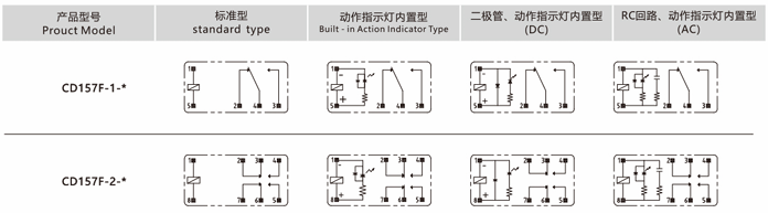
Relay sockets come in different pin configurations to accommodate various contact forms and pole counts of relays. It’s essential to match your relay’s contact arrangement (often described as “Form” or by abbreviations like SPDT, DPDT) with a socket that has the corresponding layout. Here’s a brief overview of contact form terminology: A 1 Form A relay means it has one normally-open contact (SPST-NO), while 1 Form C means one changeover contact (SPDT – single-pole double-throw, one common that switches between an NO and NC contact). A DPDT relay has 2 Form C contacts (two separate SPDT circuits, for a total of 2 poles and 2 throws per pole). Similarly, DPST usually refers to 2 Form A (or 2 Form B) contacts – essentially two separate SPST contacts that operate together. High-pole count relays exist as well; for example, a “4 CO” relay is one with 4 changeover contacts (often notated as 4 Form C, which corresponds to a 4PDT relay). These multi-pole relays typically handle multiple circuits in parallel and have a larger pin count.
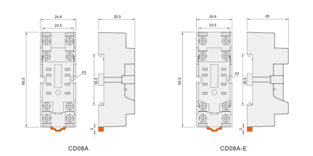
The relay socket must have the correct number of pin receptacles and the proper arrangement to mate with the relay. For instance, a standard ice-cube style DPDT relay usually has 8 pins: 2 for the coil and 6 for the two sets of contacts. It will plug into an 8-pin socket (often called an octal socket if the pins are arranged in a circle). On the other hand, a 4PDT relay (4 Form C) often has 14 pins (sometimes an 11-pin variant exists for 3PDT). Trying to insert a 14-pin relay into an 8 or 11-pin socket obviously won’t work – so you must get the exact socket that matches. Manufacturers usually group sockets by relay family; e.g., a certain series of relays in SPDT and DPDT versions will have a designated 8-pin socket, whereas the 4PDT in that series uses a different 14-pin socket base. The datasheet or catalog will specify the compatible socket part numbers. It’s good practice to use the socket recommended by the relay manufacturer to ensure proper fit and contact alignment.
Beyond pin count, also consider the mounting style of the socket, which can be relevant to contact form. Many industrial relay sockets are either DIN-rail mount or panel mount (with screws), and some smaller ones are PCB mount (solder directly to a circuit board). A PCB relay socket allows a plug-in style relay to be replaced easily on a printed circuit board without soldering. Ensure the footprint matches the relay’s form – PCB sockets will have the same pin arrangement as the relay’s leads. If your design might upgrade to a relay with more poles in the future, note that you cannot usually reuse a lower-pin-count socket; you’d need to replace it with the correct one. Thus, plan the required number of contacts (poles) ahead of time.
In summary, relay socket compatibility is about matching the relay’s contact configuration and pin layout. Always identify your relay’s contact form (1 Form A, 1 Form C, 2 Form C, etc.) and get a socket explicitly designed for that format. If unsure, consult the relay’s documentation for socket recommendations. Using the correct socket ensures each contact and coil pin mates firmly with the socket, guaranteeing reliable electrical connection to all circuits.
Key Takeaways:
Identify your relay’s contact form (number of poles and throws). For example, 1 Form C = SPDT, 2 Form C = DPDT, 4 Form C = 4PDT, etc. Ensure the socket supports that many contacts and has the corresponding pin count.
Sockets are often specified by relay series. Always use a socket that the relay’s manufacturer lists as compatible to get the right fit and pin alignment.
If you need multiple contact sets (multi-pole relays), choose a multi-pole relay socket base (e.g. 11-pin or 14-pin) that can accommodate those extra contacts.
(Learn more about relay contact configurations and socket pinouts)
Insulation, Resistance, and Safety Specifications (Dielectric Strength, Insulation Resistance, Contact Resistance)
Beyond basic ratings, relay sockets have other electrical specifications that are crucial for safety and long-term reliability. Two key parameters are insulation resistance and dielectric strength. Insulation resistance measures how well the socket’s insulating materials separate the electrical circuits. It’s typically measured in megaohms (MΩ) at a given test voltage. A good relay socket will have a very high insulation resistance (e.g. on the order of 100 MΩ or more at 500 V DC) to ensure that virtually no current leaks between isolated contacts or between the contacts and the coil. For example, one standard socket specification is ≥100 MΩ at 500 V DC. In humid conditions, this can drop, but should still be in the tens of MΩ.
Dielectric strength is the ability to withstand a high voltage without breakdown. This is tested by applying a high potential (Hi-Pot test) between different conductive parts (such as between the coil pins and contact pins, or between two contact circuits) for a short time (usually 1 minute). A typical relay socket dielectric strength might be around 2000 VAC for 1 minute. Some high-end or specialized sockets can withstand even more (for instance, 2500 VAC or 4000 VAC in certain designs), which provides extra safety margin in high-voltage applications. Dielectric strength ensures that if a voltage surge or spike occurs, the insulation in the socket will prevent arcing between circuits. When selecting a socket, make sure its dielectric strength rating meets or exceeds the maximum voltage that could be seen between the relay’s contacts and coil (or between different poles) in your use case. This is especially important if the relay will switch high voltages or if you are working in environments with surges (in which case, also consider standards like IEC 61810-1 that define test voltages for relay insulation).
Another specification to note is contact resistance – in the context of sockets, this refers to the resistance of the connection between the relay’s pin and the socket’s terminal. A new, clean relay socket typically has very low contact resistance (just a few milliohms). For example, the voltage drop might be specified as <50 mV at rated current, which corresponds to a contact resistance of a few tens of milliohms. Low contact resistance is important for energy efficiency and thermal performance: any resistance will cause a voltage drop and heating when current flows. Over time, corrosion or wear can increase this resistance, so using quality sockets (with plated contacts, strong spring retention force, etc.) helps maintain a good low-resistance connection throughout the relay’s life. When inspecting socket datasheets, you may or may not see contact resistance explicitly listed (often it’s more relevant on the relay’s spec sheet). If provided, a typical value might be something like ≤50 mΩ.
Finally, consider the standards and certifications related to these specs. As mentioned, IEC 61984 is a safety standard for connectors (which covers relay sockets) specifying requirements for insulation and creepages.
IEC 61810-1 covers electromechanical relays and indirectly affects socket pairing (for example, a combination of relay and socket might have a lower overall voltage rating if the socket reduces creepage distances. In North America, UL 508 certification on a relay socket means it has been tested for use in industrial control panels at certain ratings Using sockets that carry these approvals can simplify regulatory compliance for your project. Always verify that the socket’s voltage, current, and insulation specs are documented and meet the demands of your application’s safety standards (for instance, for machinery, for household appliances, etc., there may be specific standard clauses to meet).
| Specification | Typical Value or Range | Significance and Selection Tip |
|---|---|---|
| Coil Voltage | 5 V, 12 V, 24 V, 48 V DC; 110–230 V AC | Must match the relay’s coil rating and available control voltage. Socket insulation must handle the coil voltage (especially if it’s mains AC). |
| Contact Current Rating | 5 A, 10 A, 16 A, up to 30 A (at 250 VAC / 30 VDC) | Choose a socket with ≥ the relay’s contact amperage. Higher ratings mean heavier-duty contacts – needed for high-power loads to avoid overheating. |
| Contact Form (Poles) | 1 Form A (SPST-NO), 1 Form C (SPDT), 2 Form C (DPDT), 4 Form C (4PDT) | Socket must have the matching number of terminals for the relay’s contacts + coil. The form tells you how many circuits the relay can switch; ensure the socket is designed for that arrangement. |
| Insulation Resistance | ≥ 100 MΩ at 500 V DC (dry); ≥ 10 MΩ (damp) | Higher is better – indicates quality insulation between contacts and coil. A high insulation resistance means minimal leakage current and good material integrity. |
| Dielectric Strength | ~2000 VAC for 1 min (coil to contacts, etc.) | The maximum voltage the socket insulates without breakdown. Choose sockets with tested dielectric strength above your circuit’s highest voltage to ensure safety and compliance. |
| Contact Resistance | ≤ 50 mΩ (new, per contact pair) | Low contact resistance ensures minimal voltage drop and heat at the connection. Indicates good contact quality; important for high-current applications. |
Key Takeaways:
Insulation and dielectric specs measure a socket’s ability to prevent unwanted current flow or arcing between circuits. Look for high values (e.g. >100 MΩ insulation, 2 kV+ dielectric strength) to ensure safe isolation
Quality sockets have low contact resistance and maintain it over time, which is crucial for high-current reliability. Keep connections clean and consider periodic inspection in critical systems.
Favor certified sockets that meet IEC/UL standards for your industry. Standards like IEC 61984 and UL 508 confirm the socket’s design for safety, insulation, and fire resistance
(Learn more about relay socket safety standards and parameters)
FAQ
Q1: Do I need a different relay socket for different coil voltages (e.g. 12 V vs 24 V)?
A1: In most cases, no – as long as the relays are the same series and pin configuration. Relay sockets are generally designed to fit a particular relay package, regardless of coil voltage. For example, a given 8-pin relay base will accept a 12 VDC coil or 24 VDC coil version of the relay equally. The coil voltage does not change the pin layout. Just make sure the socket’s insulation rating is sufficient (using a standard socket is fine for low-voltage coils, but if you have a 120/230 VAC coil, ensure the socket is rated for mains voltage). Always use the socket model recommended for your relay family, and you can plug in any coil variant of that relay. This interchangeability simplifies procurement – you don’t need separate “12 V relay sockets” versus “24 V relay sockets” as long as form factor matches.
Q2: What does the Ampere (A) rating on a relay socket indicate?
A2: The amp rating of a relay socket tells you the maximum current each contact circuit can carry through the socket’s terminals. For instance, if a socket is rated 10 A, it means its metal contacts and connections can handle 10 amperes safely (usually at a specified voltage like 250 VAC). You should choose a socket with a current rating at or above the highest current your relay will switch. Using an underrated socket (for example, running 8 A through a 5 A socket) risks overheating and damage. Also note that these ratings assume a resistive load – high inrush or inductive loads effectively stress the contacts more. Always err on the side of a higher rating if in doubt. Additionally, pay attention to any dual ratings (e.g. “10 A @ 250 VAC / 8 A @ 30 VDC”); this means the socket can carry 10 A on AC but for DC the recommended limit is 8 A at 30 V due to DC’s harsher arcing conditions.
In summary: the amp rating is a hard limit per contact circuit – stay at or below it for reliable operation.
Q3: Which safety standards should a good relay socket comply with?
A3: Look for relay sockets that carry certifications or meet standards relevant to your application’s region. IEC 61984 is an international standard for connector safety that applies to relay sockets, ensuring they provide proper insulation and creepage distances for the specified voltage range. General-purpose relay sockets often also reference IEC 61810-1 (the relay standard) for dielectric strength requirements. In the US and Canada, UL 508 and CSA C22.2 No.14 listings are common – these standards cover industrial control equipment and having a socket UL Recognized or Listed means it passed tests for fire and electrical safety at its rated voltage/current. Using sockets that meet these standards is important for compliance with electrical codes and for peace of mind. Additionally, check for CE marking for EU (which would imply conformity to IEC standards and the Low Voltage Directive). In short, reputable manufacturers will specify standards like “Meets IEC 61984, UL 508” in the datasheet – a good indicator that the socket is designed and tested for safe use.
Conclusion
Selecting the right relay socket is just as important as choosing the relay itself. By understanding specifications like coil voltage compatibility, contact ratings, contact form configuration, and insulation strength, you can ensure your relays operate safely and reliably. A properly chosen socket will simplify installation, maintenance, and future upgrades – whether you’re an industrial design engineer developing a control system, a procurement specialist standardizing components, or an electrical technician wiring up a panel. Always pay attention to the details in the datasheets and opt for certified, high-quality relay bases that meet the necessary standards.
At CDGKZ Zhejiang Chuangdao Electric Co., LTD , we offer a wide range of relay sockets and holders to suit relays of all types – from small PCB relay sockets for signal relays to robust 30 A DIN-rail mounted bases for power relays. All our products meet strict IEC and UL standards, so you can trust their safety and performance. Contact us to discuss your project requirements or browse our catalog to find the perfect relay socket for your needs. Ensuring you have the right socket will give you confidence that your electrical design is built on a solid foundation – literally plugging your relays into a reliable connection. Let us help you make the best choice and keep your systems running smoothly.
