
Relay Socket Overload and Short Circuit Protection
Industrial control systems rely on relay sockets to safely interface control signals with high-power devices. However, electrical overloads and short circuits in these circuits can cause equipment failure, fire, or costly downtime. Engineers must address multiple safety factors – from current limiting and thermal cutoffs to surge suppression and emergency shutdown – to protect relay sockets and connected equipment. This article outlines common overload and short-circuit risks in relay circuits and relay socket overload protection strategies (fuses, breakers, thermal relays), highlighting industry safety ratings and guidelines to keep your systems safe and compliant.
TL;DR:
– Design relay socket circuits with integrated overload and short-circuit protection (fuses, breakers, thermal relays) to prevent overheating or arc faults[1].
– Ensure compliance with UL/IEC standards (e.g. IEC 60947, UL 508) for relay sockets and protective devices[2].
– Use surge suppressors (MOVs, RC snubbers) and ground-fault devices to defend against voltage spikes and leakage currents[4].
– Monitor current limits and implement load management (phasing, sequencing) to avoid overloading relay sockets.
– Employ alarms and protective relay integration (trip signals, E-stops) for fast fault detection and emergency shutdown.
Understanding Overload and Short-Circuit Risks in Relay Systems
Relay sockets and their wiring are vulnerable to electrical overloads and short circuits. An overload occurs when current exceeds the socket’s or circuit’s rating for too long, causing excessive heat. Without intervention, overheating can damage insulation or motors. Indeed, OSHA regulations mandate that “motor-control apparatus and motor branch-circuit conductors shall be protected against overheating due to motor overloads … and against short-circuits or ground faults”[1]. Short circuits, on the other hand, happen when a fault creates a low-resistance path (e.g., a dead short across phase and neutral). This causes a sudden high-current surge that can weld contacts, melt conductors, or trip upstream breakers.
Relays themselves do not inherently protect against these faults. Instead, relay sockets must be paired with dedicated overcurrent protective devices – like fuses or breakers – appropriately sized to the contact ratings. As one electrical expert notes, “a relay isn’t a short-circuit protection device… a fuse or circuit breaker is what you need for short-circuit protection, not a relay.” (AllAboutCircuits Forum). In practice, a typical design places a fuse or breaker ahead of the relay contacts. When an overload or short occurs, the fuse melts or breaker trips, isolating the circuit and saving the relay and load.
To prevent wiring overloads, always use the correct wire gauge and follow wiring guidelines. Conductors and socket terminals should be rated for the expected current plus margin. Wiring inspections ensure tight connections and no corrosion, which can introduce resistance heating. Label cables and limit cord use as specified by standards to avoid accidental overloads[5]. In motor circuits, advanced overload relays (thermal or electronic) can be added in series with the relay socket to detect sustained overcurrent and trip the control circuit before damage.
Key Takeaways:
– Overloads and shorts are leading causes of relay circuit damage; always fit fuses or breakers ahead of relay sockets[1].
– Relay sockets must be paired with motor overload relays or OCPDs – relays alone do not protect against faults.
– Follow OSHA/NEC wiring rules (e.g. 1910.305(j)(4)(vii)) to guard against motor overheating and short-circuits[1].
Thermal, Surge, and Leakage Protection for Relay Sockets
Beyond basic overcurrent devices, relay socket design often integrates thermal protection, surge protection, and leakage prevention to enhance safety.
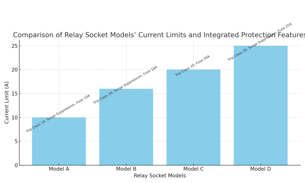
Thermal protection protects against gradual overheating. Many relay sockets incorporate or attach to thermal overload relays that simulate a motor’s heating. These relays can be bimetallic or electronic, calibrated to the motor’s full-load current (FLA) and trip time class. For example, Schneider Electric explains that when a motor’s thermal capacity exceeds 90%, an alarm activates; above 100%, the relay triggers a trip and opens its contacts[6]. These settings are defined by international standards (e.g., trip class 10, 20, etc. per IEC 60947-4-1) to prevent excessive heat buildup during extended starts or stalls. In relay sockets, temperature sensors or thermal cutouts (often labeled PTC thermistors or bimetallic strips) can similarly monitor socket temperature. If the socket overheats (due to loose connections or overcurrent), a thermal cutoff opens the circuit. Designing in thermal protection helps prevent insulation failure and fire.
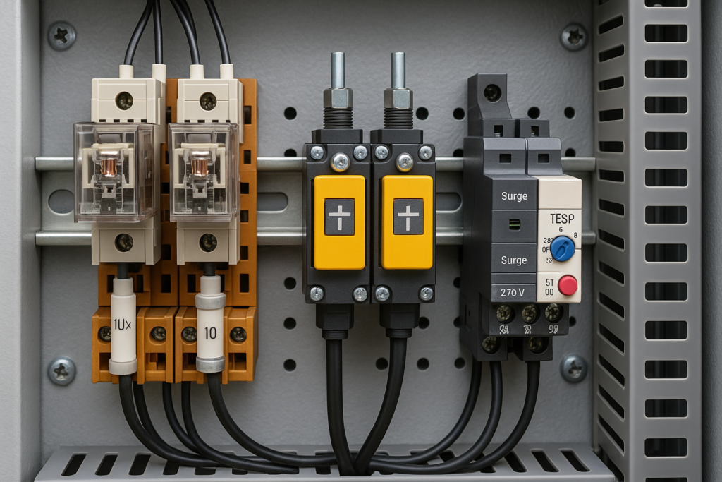
Surge protection guards against high-voltage transients from lightning or switching. Inductive loads (solenoids, motors) create voltage spikes when turned off, which can arc across relay contacts. To mitigate this, designers add transient suppressors on coils or across relay contacts. Common devices include MOVs (metal-oxide varistors), TVS diodes, or RC snubber networks. These clamp the voltage to safe levels, prolonging contact life. Industrial surge protection modules (for control panels) fit DIN rails alongside sockets. As Phoenix Contact notes, surge protective devices “prevent malfunctions and damage caused by surge voltages”[4]. They provide an “ideal solution” for protecting sensitive relay coils and downstream electronics against spikes. For example, a surge protector on a relay coil will absorb a back-EMF pulse when a contact opens, preventing it from arcing or affecting other circuits.
Leakage prevention (ground-fault protection) is also crucial. In wet or industrial environments, moisture or insulation failure can cause leakage currents. Incorporating ground-fault devices (residual-current devices or RCDs) in the panel can trip the circuit if a small current leaks to earth. While not part of the relay socket itself, proper socket design aids insulation: choose sockets with high insulation ratings (5000V or more) and IP-rated enclosures to block moisture. Designing with monitored ground straps or fault indicators helps catch leakage before it becomes hazardous.
Key Takeaways:
– Thermal relays/cutouts in series with relay sockets trip circuits on sustained overload (e.g. Class 10 trip above 100% current)[6].
– Surge suppressors (MOVs, RC snubbers) clamp voltage spikes and protect relay coils and contacts from transients[4].
– Ensure insulation and IP ratings meet leakage prevention needs; use RCDs/ground-fault devices in critical circuits.
Fuses, Circuit Breakers, and Load Management in Relay Socket Protection
Fuse Safety: Plug-in fuse holders or DIN-rail fuse blocks are often placed just upstream of relay sockets. Standard low-voltage power fuses (IEC 60269 series) provide fast-acting short-circuit protection. In IEC terms, fuses are categorized by application (e.g., type gG for general, aM for motor circuits). A gG fuse in a relay socket line ensures any short-circuit will blow the fuse and open the circuit quickly. Select the fuse current rating just above the normal load current but below the relay’s maximum rating. Because all IEC 60269 “g” fuses have similar characteristics, designers can swap brands without altering safety profiles[7]. For example, a 10A fuse on a 10A-rated relay base protects it from excessive currents. Fuses also isolate the fault location – only the blown fuse needs replacement, simplifying maintenance.
Circuit Breakers: In larger systems, circuit breakers serve a similar role with the added benefit of manual reset. Breakers sized for the relay socket’s load provide both overload and short-circuit protection. Many industrial control panels use sub-feed breakers (e.g., branch breakers) feeding groups of relays. Breaker trip curves (B, C, D curve) should match the inductive nature of relay and motor loads to avoid nuisance trips. The concept of “breaker compatibility” means ensuring the breaker’s interrupt rating (SCCR) is sufficient for the panel, and that the breaker’s frame fits the panel/rail. National Electrical Code (NEC) requires each component (including relay sockets) to be marked with its short-circuit current rating; designers verify that any upstream breaker can safely clear that fault current level.
Load Management: A key way to prevent overload is active load management. This involves sequencing relay-controlled loads so not all devices start at once, and balancing phases in three-phase systems. For example, avoid having all heavy loads (motors, heaters) on one relay circuit if others are idle – spread them across multiple relays. Many modern relay sockets can integrate with controllers that schedule or soft-start loads. Current monitoring modules or protective relays can signal when a particular channel nears its limit, triggering an alarm or shutdown. Overload alarms (using auxiliary contacts on thermal relays or separate current sensors) notify operators before a full trip. Logging and display of load currents allows trending; if a pattern of high load emerges, hardware can be upgraded proactively.
Key Takeaways:
– Always size fuses and breakers to the relay socket’s rated current, ensuring they blow/trip before any circuit component is damaged[1].
– Coordinate breaker trip curves and fuse types with relay loads (e.g., use motor-rated fuses or curve C/D breakers for inductive loads).
– Implement load management (soft-starts, sequencing) to avoid simultaneous inrush and overload.
– Internal Link: Learn more about Relay Socket Fuse Safety and Breaker Compatibility.
Safety Standards and Best Practices for Relay Socket Protection
To achieve reliable protection, follow recognized safety standards and ratings for relay sockets and protective devices. Most industrial relay sockets are designed to meet international norms. For example, quality relay sockets comply with IEC 60664 (insulation coordination) and UL 840 standards, ensuring high impulse-voltage withstand and flame resistance. The Shenler product data shows their sockets have insulation rated 250VAC, pollution level 3, and an impulse withstand of 4 kV – typical for industrial control gear. Thermal overload relays conform to IEC 60947-4-1 (and its UL counterpart UL 60947-4-1) for motor protection[2]. UL 508 (Industrial Control Equipment) and UL 1059 (Terminal Blocks) set guidelines for how relay assemblies must be built and labeled in North America.
When wiring relay sockets, use terminal blocks or connectors rated for the voltages/currents involved. Enclosures should have appropriate NEMA or IP ratings for the environment. Dedicated short-circuit current ratings (SCCR) must be calculated for the panel – this ensures that under fault conditions, the panel can safely handle the current. In fact, NEC Article 409 and OSHA rules require panels and machines to display SCCR labels. Safe design also means providing visible disconnects or lockout-tagout provisions. Control circuits feeding relays should be low-voltage (to avoid shock) and clearly documented.
Don’t neglect mechanical safety: relay sockets should fit relays snugly to avoid vibration-induced contact failure. Use retaining clips or screws as needed. Follow manufacturer torque specs for terminal screws. Keep contact surfaces clean and consider periodic inspection: loose connections can create resistive heating and early failure. The Omron safety precautions explicitly warn not to touch energized sockets and to ensure wiring is correct[8]. (Always assume power is live when working on relays.)
Key Takeaways:
– Choose relay sockets and relays with appropriate UL/IEC certifications (UL508, IEC60947, UL840 insulation) to meet safety requirements[2].
– Verify Short-Circuit Current Ratings (SCCR) for control panels and ensure breakers/fuses meet or exceed those ratings.
– Adhere to wiring standards (NEC/OSHA) for conductor sizing, enclosure IP ratings, and disconnects[1].
Advanced Protection: Emergency Shutdown and Protective Relay Integration
In high-stakes industrial settings, relay sockets are part of a broader safety system. Emergency shutdown (E-stop) circuits often use force-guided safety relays (Meeting IEC 61508/SIL standards) that cut power to multiple relays at once. For example, an E-stop can de-energize the coils of motor starter relays via a safety relay, causing all controlled equipment to stop immediately. Combining relay sockets with a safety-rated interlock ensures that a fault on one channel doesn’t disable others inadvertently.
Protective Relay Integration: Modern systems may use digital protective relays (e.g., ANSI relays) to monitor currents, voltage, ground faults, etc. These relays can be programmed to trip external breakers when anomalies are detected, even if a plug-in relay is part of the control path. In a way, the traditional control relay socket is integrated into a smart protection scheme. For example, if a ground-fault protective relay detects leakage, it sends a trip signal to cut the control power feeding the relay sockets, shutting down equipment. This integration provides redundancy: even if a relay socket failed to open, the protective relay on the breaker ensures fault clearance.
Overload Alarms and Monitoring: Many thermal and electronic overload relays have alarm contacts (sometimes with LEDs) to warn operators. When current exceeds about 90% of the setpoint, an alarm may light. These signals can feed PLCs or SCADA systems to prompt maintenance before a trip. Implementing such alarms prevents unexpected downtime: the system can alert “motor overheating” long before shutdown.
Finally, consider leakage prevention and arc suppression. Use RC snubbers or diodes on DC coils to eliminate arcing. In AC mains circuits, arc suppression relays or arc-flash mitigation (e.g., anti-ping relays) can reduce the risk of fire. Overall, treat the relay socket as one piece of a safety puzzle: mechanical, electrical, and procedural safeguards must all work together to manage overloads, trips, and emergencies.
Key Takeaways:
– Integrate relay sockets with E-stop and safety relays for rapid emergency shutdown of multiple channels.
– Use protective relays (ANSI/IEC type) to monitor faults and trigger main breakers, isolating relay socket circuits when needed.
– Leverage overload alarm contacts on relays to warn before tripping, enabling preventive action.
Conclusion
Relay socket overload and short-circuit protection is essential for safe industrial controls. By combining fuses or breakers, thermal overload relays, and surge suppressors in relay circuits, you dramatically reduce the risk of damage or fire. Ensure all components carry the correct UL/IEC safety ratings (e.g. UL508A control panels, IEC60947 relays) and that wiring follows code. For example, our 13F-2Z-B and 10F-2Z-C2 DIN-rail relay sockets are designed for 10–12 A loads, support integrated fuse holders, and meet international insulation and flammability standards. These models also feature high impulse withstand and are compatible with common protective relays.
Protect your installations with our robust relay socket solutions – request a quote today on models like 13F-2Z-B or 10F-2Z-C2 to ensure maximum safety and reliability in your system.
